Chamfers are generally made at the ends of the parts to remove the burrs caused by machining on the parts and to facilitate the assembly of the parts.
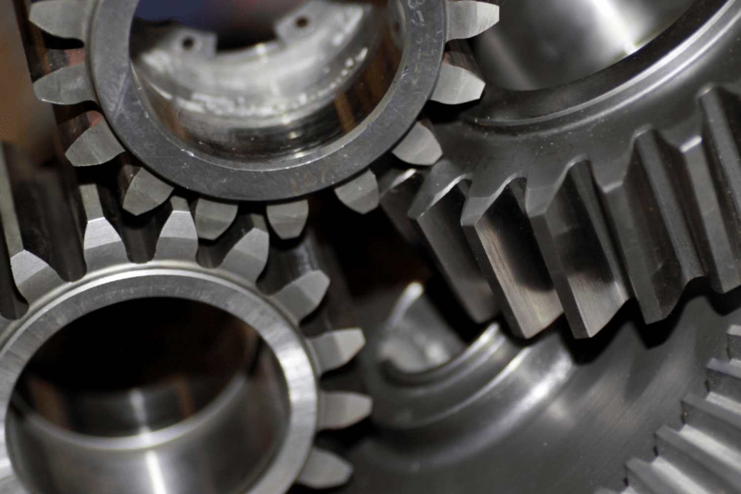
Traditionally, the chamfering of cylindrical gear profiles has been secondary to the main cutting and finishing process because this process adds cost but with little impact on the quality of the parts.
But this common perception is changing now. Awareness of the importance of the chamfering is growing rapidly as manufacturers realize that it provides significant handling and machining advantages for the downstream as chamfers and gear flanks remain burr-free and can be produced to the required specifications.
With the convenience of installation, chamfering mainly refers to make a slope of a certain length along the shaft and hole in machining at an angle of 30°, 45°, 60° and etc. Commonly used marking methods (for example, C1 chamfering angle is 45°, length is 1mm). Although the chamfer rolling technique is still the most common one, what excites manufacturers most is the current new chamfering technology under exploration. These technics meet their most demanding requirements while significantly reducing operating costs.
Economical method: chamfer hobbing
The development of new tool technology has brought the chamfering hobbing tool into life. Nowadays the chamfer hobbing is the first choice of machining process for chamfering and deburring high-volume gears, but the process is limited to spur gears and is constricted in performing current chamfer specifications. The advanced chamber hobbing technology made a contribution to the qualitative leap of the chamfer cutting technology.
The chamfer hobbing tool cuts the chamfer on the left and right sides.
Another advantage of the chamfer hobbing process is the long tool lifespan. It is very common for chamfer hobbing tools to produce more than 30,000 parts before they need to be re-sharpened, which has greatly reduced the time required for changeovers. This is benefited from the ability of the chamfer hobbing tool unit to gradually move the position of the chamfer hobbing tool along its tangential axis, thus maximizing the use of the cutting area on the flank of the hob.
When re-sharpening is required, dressing of chamfer hobbing tools is similar to dressing of standard hob cutters and can be performed by using existing hob dressing or capabilities of re-sharpening. Different from conventional hob cutters, the new chamfer hobbing tool features an asymmetric tooth design: the active flank is used to cut the desired chamfer shape, and the passive flank is designed to avoid contact with the opposing flank. Therefore, there is a dedicated chamfer hobbing tool for each flank in the chamfer hobbing process.
By using these separate dedicated chamfer hobbing tools to cut chamfers on the left and right sides in a generative pattern, the users can meet the widest range of gear performance goals flexibly and accommodate applications with different geometries on the gear face. Each chamfer hobbing tool can be designed to produce vertical or parallel chamfers, with or without root chamfers. What’s more, chamfer angles similar to those typically produced during chamfer rolling (e.g., 15-30 degrees for blunt edges and 25-45 degrees for sharp edges) can be achieved.
The flexible method: fly-knife chamfering
The burrs are normally generated on the edges of the end teeth when machining meshing teeth, and these burrs must be removed for various reasons, also, deburring alone is not enough for many cases. There is such a risk if the tooth edges are not machined: the tooth edges will become glass hardened and then crack under load due to excessive carburization during the subsequent hardening of the meshing teeth. So, the tooth edges should be chamfered. Among many techniques, plastic reshaping of the tooth edges into chamfers is currently the most popular one, in which the material of the workpiece rolls in the region of the tooth edges by means of a chamfering wheel to form and displace the toothed joint. There are also cutting methods in which chamfers are created on the tooth edges by cutting. For these methods, flying knives whose cutting edge shape is independent of the tooth profile can be used to guide the position of the fly knives (including axial spacing and pivot angle) appropriately during the chamfering process, thus allowing the cutting engagement to roll along the profile shape of the workpiece meshing teeth. A disc-shaped chamfering tool has a similar appearance to a fly cutter, and the cutting-edge shape of its teeth depends on the meshing teeth. In this profile cutter, the profile shape of the cutter teeth matches the backlash profile of the workpiece meshing teeth. The cutter teeth cut out the chamfer profile of the entire tooth gap during the chamfering process, which creates a rolling motion between the profile cutter and the meshing teeth, so that the cutter tooth cutting immediately following the cutter tooth which can follow the backlash of the initial cut.
CONTINUE READING
Related Posts
In industrial machinery, V-groove pulleys are a critical component, transferring power efficiently and ensuring the smooth operation of various mechanical […]
Spur gears are among the simplest and most widely used gears in mechanical engineering and industrial applications. Their straightforward design […]
Taper lock bushes are essential components used to securely attach pulleys, gears, and other mechanical elements to shafts. Their design […]


